Biology - Electronics - Aesthetics - Mechanics
Main | Electonics | FAQ's | Definitions | Solar engine | Nervous Networks | Advanced Nervous Networks | Motor drivers | Miscellaneous | Links
 The Solar Engine
Introduction
A solar engine is a kind of control circuit that takes micropower and converts that micropower into more powerful pulses. These more powerful pulses are usually used to power motors, but can be used to power other motion-creating devices, such as, Nitinol wire. The first solar engine was built by Mark W. Tilden in late 1989[1]. Let's attempt to understand the need for such a circuit with an analogy that will illustrate the need and show the solution.An Analogy
 Let us suppose that we have a source of water and we want to use that water
source to perform some work. For grins, let's say to grind coffee. Now our water
source is not the most plentiful, but it does have a constant stream. So how can
we devise a way to utilize this small, yet constant stream?
The figure to the right depicts my solution,
called a WaterEngine.
Let us suppose that we have a source of water and we want to use that water
source to perform some work. For grins, let's say to grind coffee. Now our water
source is not the most plentiful, but it does have a constant stream. So how can
we devise a way to utilize this small, yet constant stream?
The figure to the right depicts my solution,
called a WaterEngine.
Now, let's go through the system briefly to describe the components and then we can look at the operation of the system as a whole. First we have (a) which is our source of energy, water droplets. Next, our collection device, (b) which funnels most of the water into the tank, (c) with a little spillage (loss of energy). Now once our tank gets full, we have a series of mechanical controls (d,e,f and g) that are activated when the tank is nearing the rim. This control mechanism controls the flow of water to the outlet, (h) and over the water wheel, (i), whereby the water's energy (potential) is converted into the mechanical energy required to spin a wheel via a belt.
So how does this control mechanism work? Well, when the tank's water level is nearing full, some water begins to leave the tank via the pipe, (d). The purpose of this "level detection" or "trigger" is to initiate the emptying of the tank, (c). So once the water reaches the triggering level, water flows through (d) and into the box (e) (with some minor spillage into (g). The device in (e) is essentially a spring valve that activates a larger valve in (f) to allow the water to flow from (c) through (f) and out (h). Now of course, once the water begins to flow, the tank's water level will lower and essentially cease the flow of water out (d), which triggers (e). However, our valve (e) will be activated by the flow of water coming out of (c) and through (f) up through (g). This mechanism will stay active until the flow of water stops activating (e) through (g).
The Circuit
Theory of Operation
Essentially the SE is a modified SCR (Silicon Controlled Rectifier) with supercritical feedback. I would like to point out that we are interested in the electron current, as opposed to conventional current (that is, the movement of positive charges, opposite to electron current), unless otherwise stated as so.The following timeline are the events and circuit characteristics while charging and discharging:
So how do these diodes and transistors work?
- EVENT - Beginning of charging cycle
- Capacitor C1 begins to charge due to current from the solar cell and the voltage across C1 rises
- Q2e is positive, which is required for conduction. However, the base, Q2b is also positive - from the resistor through the motor. Thus, current cannot flow from Q2c to Q2e.
- In order for current to flow through Q1 (Q1e to Q1c), Q1b must be positive and Q1c must be negative. Otherwise, the collector-base [ N | P ] junction is basically a diode being reverse-biased. When there is no voltage connected to the base of an NPN then Q1 is equivalent to two diodes connected back-to-back, which do not conduct. (is this correct?)
- Once the voltage of C1 reaches the trigger voltage of D1, which is forward biased, current flows through D1. (why at that trigger voltage?)
- The current flowing through D1 establishes a source current from Q2b to Q2e. This in turn causes a greater current to flow from collector (Q2c) to the emitter (Q2e), thus allowing Q1b to see positive.
- The current flowing from the Q2c to Q2e, causes a similar flow of current in Q1 from Q1e to Q1b, since Q1b is now positive.
(Recall, that if a small voltage is applied to the base -- enough to remove the depletion layer in the emitter-base junction, current flows from emitter to base as in a diode)
- This small amount of current through Q1e to Q1b induces a larger flow of current from the emitter (Q1e) to the collector (Q1c).
- The current flowing from Q1e to Q1c goes throgh motor, M, causing it to go spin.
- EVENT - SE triggered, Beginning of discharging cycle
- EVENT - Motor turns on
- While the current is flowing through M, the voltage across C1 falls
- EVENT - voltage across C1 falls below trigger point of D1
- The base of Q2, Q2b is being feed current by way of D1 and also by way of R1. Thus, when the voltage falls below D1's trigger point, D1 stops conducting and current continues to flow into Q2b (and through to Q2e) by way of R1. Thus keeps Q2 on, which in turn keeps Q1 on, which allows the motor to run. And so on, until the motor resistance / load creates a high resistance whereby it essentially halts the cycle.
- Here you will recognize that this behavior is very much like that of a Silicon Controlled Rectifier (SCR), in that load is turn ON by one method and OFF by another. With an SE, it is initially turned ON by the trigger, D1; and turned OFF when the motor's inertia and resistance is too large.
- (note: Q1 is the main driving transistor switch that allows the current from C1 to flow through the motor M. Q1 can be doubled (see Darlington amplifier on p. 234 of gold electronics book) or replaced with higher current transistors - like the 2N2222.)
A diode is normal built by touching two different pieces of semiconductor together to form what is called a "p-n junction." Semiconductors are materials that are in between good conductors and good insulators. A pure semiconductor is a very poor conductor of electricity. With careful chemical processing, a semiconductor can be made into n-type semiconductor--a semiconductor that contains a small number of mobile electrons that permit it to carry electric current. With different processing, a semiconductor can also be made into p-type semiconductor--a semiconductor that contains a small number of mobile holes for electrons that permit it to carry electric current. It may seem strange that a hole for an electron can allow electricity to flow, but imagine a highway packed with cars (electrons) bumper to bumper. If there are a couple of empty places (holes) in the bumper to bumper traffic, then cars (electrons) can rearrange enough that the traffic can flow. Both mobile electrons and mobile holes allow these two chemically-treated semiconductors to carry current.
When an n-type semiconductor touches a p-type semiconductor, a diode is formed. The mobile electrons at the edge of the n-type semiconductor flow over the boundary (a p-n junction) and fill the mobile holes at the edge of the p-type semiconductor. This rearrangement creates a depletion region--a region near the p-n junction in which there are neither mobile electrons nor mobile holes. This depletion region normally won't carry electricity at all. But if you push electrons onto the n-type semiconductor, they will flow toward the p-n junction and replenish the missing mobile electrons. As these mobile electrons approach the p-n junction, they will repel the electrons that are filling the mobile holes on the p-type side of the junction and reopen the mobile holes. Electrons will begin to cross the p-n junction and current will flow through the diode. However, if you push electrons onto the p-type semiconductor, they will fill even more of the mobile holes there and the depletion region near the p-n junction will grow larger and more uncrossable. No current will flow through the diode. Thus a diode (a p-n junction) only carries current in one direction--electrons can only flow from the n-type semiconductor side to the p-type semiconductor side.
There are many types of transistors, so I will only describe an n-channel Metal-Oxide-Semiconductor Field Effect Transistor, or n-channel MOSFET. In this device, three layers of semiconductors are sandwiched together: an n-type piece (the source), a long, thin p-type piece (the channel), and another n-type piece (the drain). Two p-n junctions form between these three components and, since the junctions are arranged in opposite directions, they completely block current flow from the source through the channel to the drain. But a metal surface (the gate) that's separated from the channel by an extremely thin layer of oxide insulator can control the number of electrons on the channel material. If you put even a tiny bit of positive charge on the gate, it will attract electrons onto the channel and turn it from p-type semiconductor to n-type semiconductor. When that happens, both p-n junctions vanish and current can flow from the source to the drain. The MOSFET goes from being an insulating device when there is no charge on the gate to a conductor when there is charge on the gate! This property allows MOSFETs to amplify signals and control the movements of electric charge, which is why MOSFETs are so useful in electronic devices such as stereos, televisions, and computers.
-Source unknown.
The embryonic circuit of the BEAM robotics philosphy is an energy storage circuit known as a Solar Engine(tm) (abbreviated SE) - a simple relaxation oscillator. This particular design (called a Type-1 SE) stores energy from a small power source (e.g., a solar cell) in a large capacitor until a preset voltage threshold is reached, whereby the energy is released into a motor. This is the basic device, however many variations have stemmed from this design, incorporating various motor devices, triggering circuits and mechanical layout.
Following Tilden's philosophy, the circuits that I have constructed are made of recycled parts, calculator solar cells, transistors from radios (sometimes), motors from various sources (old volt-meters, pagers, toys, etc.) with efficiency, simplicity and mechanical beauty being my primary goals. It is like bringing life back into unwanted tech-junk.
A Note from the Author
There seems to be a lot of questions and problems in replicating the device on this page. Steven Bolt of the Netherlands has come up with a potential solution called SunEater. The best advice, from my experience, is to first create the circuit described following the author's specifications and design parameter. Experiment with the circuit once you have completed a functioning circuit. If you still have problems, E-mail the list or the author. A good course of study to those just beginning in BEAM robotics would be to start out with a solar engine based device, before moving on towards more complicated circuits, such as nervous networks, like the microcore.
Relevance to Nervous Networks
The Solarengine(tm) is just a transistor implementation of a Nv "Monocore" that can drive a motor directly without the need for additional buffering (as in the more complicated Nv Networks).In fact a SE behaves very much like a nervous network. The SE has an upper threshold (trigger voltage) and a lower threshold (shut off), and the duration of the state change (pulse) is directly affected by the motor load. In addition the "off" state (really the time held below threshold) is affected by what's feeding it (in this case the solar cell/trigger, in a nervous network - the previous Nv). So, in essence you have a quasi-chaotic phase/state-based oscillator threshold device that is self-attenuating with respect to environment in a dynamic fashion. See the FAQ for details on Nv Networks (NvNets).
Required Parts
Please when first building a SE, use the parts that I recommend. Experiment with part substitution once you have a working circuit.M - a motor, I used anything I could find with an armature and a coil of wire. Motors with small power requirements usually work great (i.e., 3 volts at a low current rating). Coils (very fine wire with lots of turns), Nitinol wire (aka, "Muscle Wire") or diodes can also be used - however, a ten MegaOhm load is not a replacement for the motor. (A word of warning: some small recorder motors have a built-in capacitor of about 20 nanofarad. The 2-transistor FLED SE won't work with such a motor - it will start to oscillate, sometimes audibly. Without a scope, the typical symptom is `hangup' in reset. The SE fires once, then stops, the voltage over the storage cap remaining at less than 1.0V. Both SunEaters are immune to this problem, and will run such motors.)
C1 can be anywhere from 2,200�F to 47,000�F (or as high as 10 Farad). Depends on your application and timing requirements.
R1 can be anywhere from 1.8k Ohms to 15k Ohms. The smaller the resistance the better the starting power of M, but more energy is lost in the transistors.
Q1 - a NPN transistor, general-purpose like the 2N2222, 2N3904, etc. Cheap and easy to find.
Q2 - a PNP transistor, general-purpose like the 2N2907, 2N3906, etc. Also cheap and easy to find.
D1 - a theshold device, such as a small signal switching diode, e.g., 1N4728 to 1N4731.
Since a single diode would trigger at [0.6 - 0.7] volts, we need to use multiple diodes in series.
Arranging the diodes in series would give you an increased increased "trigger" voltage, thus
for example, two diodes would trigger at [1.2 - 1.4] volts and three diodes in series
would trigger at [1.8 - 2.1] volts.
Variants:
- (1) can be substituted with a Zener diode-mc4742, here the Zener starts clamping at v+ 0.7 volts, eventually triggering the PNP transistor, then triggering the NPN transistor, and will lock so long as the motor is moving, OR,
- (2) a Flashing LED, which is a more efficient variant. See Zener diodes draw more and more power as they reach the "trigger" point. If the solar cell can't provide enough power to overcome this extra current draw, it'll stabilize at a point where the Zener "leaks" as much current as the cells provide, OR,
- (3) a voltage trigger, such as the 1381 (find them at Digikey, it is a 3 pin device, and monitors one voltage source).
Solar Cell - like a 24x33mm Sunceram Solar cell or a few solar cells swipped from calculators. I have also used several small photodiodes, which generate 0.4 volts each, in series they generate higher voltage (e.g., 2 in series generates ~0.8 volts, and 3 in series generates ~1.2 volts, etc.).
Construction
Well for those that are good at soldering, the circuit is best put together in a free-form kind of structure, that is, without any circuit board. See this alternative set of plans and picture below depict the physical layout of the solar engine-the layout is right above the circuit diagram. I believe it is the best layout, and does not require a printed circuit board (PCB). As for the mechanical layout, the best advice I can give is to start building, because your first will not be your best. When you have completed your mechanism, don't cabbage it for parts, move on to the next so that you can have a living history of mechanisms.
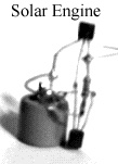
A solar engine using the free-form
layout without a PCB (without motor)
Debugging Information and Questions
Basic Debugging
Q: Is there a way to debug one of the 2-transistor/1 FLED Solar Engines?
A: (contributed by Richard Weait and Dave Hrynkiw)
- Check that your components are in the holes that they started in (especially if you share your lab with other lifeforms.)
- Check that they are in the holes that they are in. Breadboards can have reliability problems.
- Vcap <1.0 Vdc?
- Check V (solarcell-open circuit)
- Check NPN and motor.
- Vcap climbs to V solarcell but no trigger?
- Check connection to transistors
- Check LED and PNP.
- Vcap climbs and drops, motor doesn't move?
- Check motor shaft / efficiency.
- If you can see the FLED blinking, that means something's not right. Sounds like it may be in backwards. Cathode goes negative (the shorter leg, or the one closest to the chamfer on the side of the lip on the FLED). It could also be an indication of power-hungry motor - try an efficient motor, like a pager motor.
Solar Engine Cycling
Q: My Solar engine takes forever to cycle (power up, discharge, power up,...)?
A: Sounds like a current-generating problem to me. Solarcells from calculators are notorious for good voltage but produce low-current. Try wiring up the cells so they generate about 4 volts, which should triple the current.
Large Capacitance, Low Current Generating Source
Q: I substituted a huge 2F capacitor for C and my solar engine doesn't work now?
A: You might have to wait days if you have a poor current (say, two 18 uA at 1.3V cells in series) generating solar cell (and supposing you have a blocking diode-to prevent the discharging of the capacitor through the solar cell). A solution might be to larger solar cells (say, 3.5V at 6mA) or gang them in solar cells in parallel for more current.
Testing Transistors
Q: How do I test Transistors?
A: Although transistors are very sturdy, they can make debugging a circuit quite painful if they are defective. For those of you with multimeters that don't have a "diode check" function, put your meter on its highest resistance scale. Testing an NPN, such as the 2N3904, with your positive probe on the base (middle lead), and the negative probe on the one of the remaining leads. If it shows infinite resistance, it is defective. Then switch the negative probe to other outside pin and check it too. If should show some resistance, about 28-34 ohms. In summary, an NPN transistor is checked with the leads arranged Negative, Positive, Negative. For a PNP transistor, do the same, except put the negative probe on the base (middle lead) and use the positive probe to check the outside leads. The same resistance values should show up.
In summary, a good resistor will have the following characteristics in terms of the resistances between the leads: emitter(e), base(b) and collector(c)
| Transistor Type | Rbe | Reb | Rbc | Rcb | Rce | Rec |
| high | low | high | low | high | high | |
| low | high | low | high | high | high |
Note: Rbe means the base positive with respect to the emitter, Reb the emitter positive with respect to the base; and the other junctions have similar designations.
Why Not an SCR?
Q: Why do all the solar engine schematics I've seen use
a PNP & NPN transistor to make a modified SCR? Why not just use a real
SCR? Wouldn't it be a lot smaller?
A: An SCR is a single package designed to stay on when turned on. With the 2 transistor package, you can tune it for optimal performance (the bias resistor) depending on the application or motor. Also, you can substitute for larger power transistors (2N2222 NPN) and keep the smaller signal transistor (2N3906). And I'm not sure if there are any SCRs as easily available as the npn/pnp combo that run at such low power.
Solar Engine Not Firing
Q: (Using a battery) The circuit charges great to about 1.7 volts, then the FLED starts flashing. The circuit continues to charge to the max voltage, and the FLED is flashing happily, but the transistor never fires. I know the circuit works otherwise because when I short across the FLED the motor spins and everything starts over. I just can't get the FLED to fire it. I have tried replacing the 2.2k Ohm resistor with a 5.6k Ohm - same results, then with a 1.0k Ohm resistor - same results. I then replaced the 5.6k Ohm I was using to limit current from the batteries with a 1.0k Ohm- same results, the circuit just charges faster.
A: First, two comments:
- This is a transistor circuit which is a current amplifier.
- The FLED circuit requires about 0.75mA +/- 0.25mA to trigger the circuit.
Electro-Magnet Solar Engine
Q: Some questions on a Magbot-style solar engine, which generates a magnetic field with a large inductance coil every time the SE fires.
A:
Wire type for the coil?
As fine a wire as you can get. Not heavy wire, probably too heavy and not enough inductance.Core for coil?
Air core, smallest hole possible.Size of the coil?
Largest diameter possible. Look for something about the size of nickel to a quarter.Strength of magnet?
Strong as possible. Try a rare-earth magnet.Does the SE need a different resistor value, which also determines its efficiency and starting power?
Depends on the inductance of the coil you use. Start low (i.e., 47 Ohms) and up the value until it starts working flakey. Then come down down about 25% in value.
Capacitor Internal Resistance
Q: Can anyone here tell me how to go about measuring the internal resistance of a capacitor?
A: There is a difference between self-discharge and internal resistance. The latter can be determined from the time it takes for the voltage the drop a certain part of the original value when the capacitor is shorted. (To find out the first, you also time the voltage drop, but you leave the terminals isolated.)
A couple of calculations that may be useful:
After time T, the capacitor is discharged to 0.37 * U (where U is the original value)
uC is the voltage after t seconds of discharge
It may be better to short the cap using an external resistor, and calculate what *extra* resistance the cap offers.
Debugging Tip
Double check the orientation of your FLED - cathode (side with chamfer) goes negative. Solarengines will work with the FLED in backwards too, but at reduced efficiency.Ideas and Hints
A circuit that charges a large (many Farad) capacitor during the day and at night (at least for a few hours) flashes an LED. The trick is getting the circuit to activate at sunset.
A circuit that uses a coil of wire and a magnet to produce some sort of motion (use your imagination to produce something useful). Like Tilden's Magbot.
Aim for a more efficient motor and a low trigger voltage, this will keep you in the linear part of the charge curve.
Several medium to long bursts of energy are better than a whole lot of small ones.
In solar engines utilizing flashing LEDs (FLED), shielding the FLED from intense light makes it much more reliable. A light-emitting PN junction is also influenced by external light. This didn't used to be a problem, but lately there seems to be quite a few FLEDS that are sensitive to light, causing them to lock up. Try using some black electrician's tape or black heat-shrink to cover up the FLED.
Notes and references
[1] The first BEAM bot was "Solaroller 1.0". It was invented Nov 10, 1989 in Waterloo, Ontario at the University of Waterloo MFCF Hardware Lab (after hours) by Mark W. Tilden. It was made from two dead calculators, two dead Phillips cassette mechanisms, and several parts from Laser-printer cartridges. It has o-ring drive of the back motors, with a twist-castor as the front wheel. It would sit around for as long as 20 minutes before making a six-inch sprint, using a Happy-Birthday module as a push-pull trigger for the two 2N2222 style solarengines (very leaky, but all Tilden had at the time). Two weeks later, the first solaroller was born. Yes, backwards, but Tilden is not one for following instructions.
Brian O. Bush / bushbo@mediaone.net
Updated: Dec 2nd, 1998