Biology - Electronics - Aesthetics - Mechanics
Main | Electonics | FAQ's | Definitions | Solar engine | Nervous Networks | Advanced Nervous Networks | Motor drivers | Miscellaneous | Links
Motors and Motor Drivers
We need to connect the Nv net (MicroCore) to the motors. However, the Nv net itself cannot drive the motors. Thus, we need a motor driver. A low current solution is to use 74x245 (an Octal bus tranciever designed for data transmision) as a motor driver. The MicroCore does it's best when driving through a Low gain system. See details on Miller's site.For higher current motors and check out Tilden's H-bridge.
[1] Motors
Motors. What is it about motors that we desire? Well, movement of course. There are two main types of movement pointed out by Mark W. Dalton (mwd@cray.com):
- Circular
- Linear (Nitinol)
other variants of the above are:
- Motor with a "crank shaft" can produce a linear motion like pistons or like wings.
- A worm gear can be used to move across a the gear, commonly done using a long threaded bolt and something attached to a nut. When the bold is turned the nut (and whatever it is attached to) moves linearly. This is something I have seen in a lot of legged devices (slow but lots of torque). This also has problems, because the motor cannot feed back to the circuit.
- A magnet with coils
[2] Tilden's H-bridge
Q: What is Tilden's H-bridge circuit (i am assuming it is not a traditional H-bridge)?A: Not only is his H-bridge a little out of the ordinary (depending as it does on the complementary outputs of a couple of Nv neurons) but he apparently has come up with a newer one that is even more energy-efficient. This circuit depicts Tilden's H-bridge, no fancy protection though, since an input of 0,0 = Smoke. This H-bridge sketch is accurate but it leaves out a few things, namely the 74C139 which is used as a dual-decoder to avoid the double-trigger = smoke option, and to serve as a dynamic break controller. Note: Inputs to the trigger transistors should have at least 50k Ohm resistors on them.
Excerpted from Principa Robotica by Mark Tilden is a section on Biomech Motor Bridges.
Q: I was using Tilden's H-bridge with a 74LS139, worked fine, until I added the transistors. It seemingly cannot drive the transistors. What is wrong?
A: Sure it can, just make sure the enables on the 74x139 are tied low. You don't really need the 74x139 though, since the MicroCore can drive the H-bridge just fine on its own. If you've wired for 4 Nv then make sure the inputs of the bridge are tied to diagonally opposite corners so you will never get the 0,0 = smoke condition.
Q: I set up using just transistors, MicroCore will drive in one direction? For some reason the feedback is seemingly so great from one of the transistors the MicroCore skips into saturated mode. Is it the transistors?
A: No, it is not the transistors. Your input bias resitors are too small. Should be at least 47k Ohms (or so) or you run into problems with the double aplification effect knocking your power so low as to reset the MicroCore. Make sure your input resistors are 50k+ Ohm and put a 22 µF capacitor on the power pins of your 74C14.
As far as transistors goes, just about anything will work, as long as the four power ones are all rated around the same thing your cool. You can use tiny ones for the trigger transistors cause there not doing much. The 2N3904 and 2N3906 transistors work great for small motors.
A Cheaper H-Bridge Design - the Zoelen Bridge (Z-Bridge)
Copyright A.A. van Zoelen
All rights reserved
December 1997Problem
I need to drive two motors, 30 mA each. If I build Tilden's H-bridge, I need the following:Altogether it will cost about US$ 10 and much room on my circuit board. The design is really great but i don't have to room for it and i like to spend less.
- 1 x 74x139
- 4 resistors
- 4 diodes [optional.]
- 12 transistors
Solution
You can drop all off the transistors and resistors if your motors don't drain too much current. You only need a 74F139 or 74S139 NOT the LS version. The chip can provide peak currents up to 100mA for a short time (<1 second) and to one output at a time. This is for normal connections. I don't know how far you can go with this misbehavior. It's nothing special, but you get the idea how it is done.Circuit Layout
                   +---------- Reverse
         Motor     |  +------- Forward
  GND     |  |     |  |  +---- Engage (connected to GND = YES)
    |  |  |  |  |  |  |  |
  .-+--+--+--+--+--+--+--+-.
  | 8  7  6  5  4  3  2  1 |
  |                       [|
  | 9 10 11 12 13 14 15 16 |
  `-+--+--+--+--+--+--+--+-'
    |  |  |  |  |  |  |  |
       |  |     |  |  |  Vcc
      Motor     |  |  +------- Engage
                |  +---------- Forward
                +------------- Reverse
Comments
(reply from Tilden) It is something special. It involves minimality, expandability, elegance, and a horrible, dangerous violation of the original purposes of the chip.It's a biomech beaut. I think we should call it the Zoelen Bridge and, with permission, would like to enter it into the lexicon.
The problem with the Z-bridge is that it's standby power (10 - 40 mA for the F and S TTL series) is considerable for solar designs, so it restricts it primarily to battery powered robots. However, it is highly likely that the more efficient 74ACT139 version of this chip can drive and withstand significantly higher inductive loads, and as the 139 is stackable and symettric, all input and output leads can be folded over from one side of the chip to the other to increase the power capacity. This means the Z-bridge can be glued right on the motor itself with minimal modification, reducing lead losses and increasing design flexibility.
As well, the leftover outputs can be used to drive "motor-active" LEDs right on the chip without current drains on the MicroCore outputs, giving necessary process status during MicroCore convergence.
A futher advantage is that by using diodes from the four motor drive outputs with paralleled select inputs, permutations on enable states will give different current drive levels. This means trivial and cheap digitally selectable speed control using as many stacked 139s as you want.
Inexpensive small motor drive with enable, short protection and cascadeable control in a commonly available 16DIP package. Very nice indeed, and I can't believe I've been looking at it for years and never made the connection.
(later comments) I am pleased to announce that the 74ACT139 Zoelen bridge works excellently as an all-in-one, foolproof H-bridge for driving up to 300mA motors between 2.5 and 6volts.
A 47k pull-down resistor is recommended for all enables and A and B inputs as the ACT is a high input impedance device. Current efficiency is not great, but more than adequate for battery powered designs. Standby current (enables high) is less than a milliamp though, so don't count out solar operations if your capacitor is big enough to deliver the juice.
Diode assisance from one side to the other is limited as the 139 is not a tri-state device, however 20% power gains can be made with 4001 diodes from the (dis)abled side outputs to the enabled side inputs if the disabled side takes the negative diode rails. More work will have to be done to see if cascaded 139s can give variable motor power.Anyway, it works, it's cheap, CMOS compatable, and simple as hell.
Another H-Bridge Design

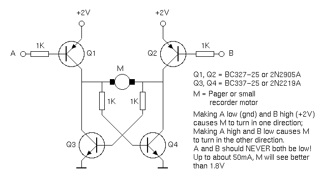
If your motors don't need too much current, you might use a transistor H driven by 74HC logic. Up to about 50mA motor current, the above circuit will drop less than 0.2V. The active base current (A or B low) is about 1.3mA, which a 74HC output will easily sink.
The circuit is known to give this performance with the BC-type transistors; the 2Ns are best guess at equivalents.
from Steven Bolt, sbolt@xs4all.nl
Yet Another H-Bridge Design

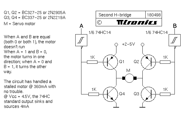
This circuit may be of interest, as it has no "0,0=smoke" mode of failure. When signal points A and B are equal (both 0 or both 1), no current flows. Only when they are unequal does the motor run forward or reverse. It has been tested up to 360mA motor current with no trouble (74HC outputs remaining at Vcc and gnd), using BC327 and BC337 transistors. Judging by the family data, 74HCT should give the same performance as 74HC in this case. The 2N2905 and 2N2219 look like good equivalents of the BC-types.
from Steven Bolt, sbolt@xs4all.nl
[3] Nitinol Wire
As for the "Muscle Wire" , it takes a considerable amount of current, and still-worser-yet it takes time to react. Both of these equate to too much energy to realize BEAM applications (humble opinion). It is really neat material, but has little published applications (probably due to the low efficiency, said to be 2% at best). It draws too much current to be used on a mobile machine, at least if its solar powered. If you use solar power it would be a very low-duty-cycle option. If you don't mind a tether (shudder) it's possible if you use a high current driver of some sort (like a 2N2222). Tilden has built a few (3, i think), Andrew Miller has built one. Others?
Copyleft 1996-1998, Brian O. Bush
Brian O. Bush / bushbo@mediaone.net
Updated: Apr. 18th, 1998