Biology - Electronics - Aesthetics - Mechanics
Main | Electonics | FAQ's | Definitions | Solar engine | Nervous Networks | Advanced Nervous Networks | Motor drivers | Miscellaneous | Links
Nervous Networks
Contents
[1.0] Introduction to Nervous Networks
This document is the Nervous Network FAQ (frequently asked question) list for those who are seeking knowledge on building, debugging or modifying a MicroCore Nervous Network or other nervous network configurations. Please, see the plans for building a two-motor MicroCore walker by Andrew Miller and other introductory reading material can be found at the FAQ on Nervous Networks.
Feedback to a Nervous Neuron
Q: When a MicroCore gets feedback from a motor's load, from what I understand, if the motor experiences increased load, this draws more current from the available power supply and lowers its voltage. This causes a change in the MicroCore's time constants. My questions are: does an increased load cause the time constant to shorten (the Nv loop speeds up) or lengthen? Does this affect all Nv's in the loop or just the one driving the motor with the increased load (Multi-process situation)?
A: In the standard Miller configuration, yes. If you want individual attenuation (as in the walkman design by Tilden), then a 4.7k Ohm resistor placed across the buffers will give you the second order effects of individual temporal adaptation. The idea is to load the output driver of a Nv cell so that the signal passed on to the next cell is shortened. These traveling effects result in the more exotic adaptive behaviors associated with advanced Nv designs.
Q: How do I create large Nv Networks (i.e., larger than four Neurons):
A: Simply, keep going output to input and change to the next chip when you run out.
o -> o -> o -> o -> o -> o -> o -> back to the first Nv Neuron(Tilden) As some may be finding out now, homogeneous Nv systems loose phase competency at large integration scales. That is, adding an active head or other form of controller to a walking body and keeping it competent is not as trivial as it sounds, and the problem gets worse the more diversity levels one adds.
Q: The pulses in my Nv Net are too short. How can I increase the pulse width? Do I increase the value of the resistors, capacitors, or both?
A: In short the delay, t approximately equals R*C. If you want your delay to be longer than the current delay, you can increase your capacitance or the resistance. There's no need to increase both.
Tip: Keep the capacitors constant and vary the resistor values.
Motor Configuration
Q: I don't know if I got the motor polarities right, how should I check it for errors?
A: Motor polarities are based upon the motors, the gears, and orientation in the final robot configuration, so don't sweat the phasing until you've got the design crudely walking, then you can just swap two wires if it's moving backwards. What you can say is that the process propagation is counterclockwise around the loop. It is confusing, that's why if you read "Living Machines", you'll see why Tilden came up with a symbol lexicon which makes it easier to understand:
        o               - reset neuron
        |
        v
        o--00--o        - forward motor
        |^    ^|
        | \  / |
        |  \/  |        - process flow path
        |  /\  |
        | /  \ |
        v/    \v
        o--00--o        - rear motor
where o is a neuron, and 00 is a motor. Graphically, it's a lot easier to deal with.
Microcore Frequency
Q: What is a general rule of thumb (if there is one) for the frequency of the microcore?
A: The approximate time for the propagation can be calculated from the standard formula:
T = R * C Where:
T is in seconds
R is resistance in Ohms
C is capacitance in farads
Thus,
T = (1,000,000 ohms) * (0.000 000 22 farads)
T = 0.22 seconds delay at each Nv,
Therefore, for the entire Nv network propagation time is,
T * 4 (the number of Nv neurons in a microcore) = 0.88 seconds
This is should be close to what you are observing.
Manufacturing Tolerances Problem
Q: I've interfaced the motors with the 74ALS245's and they are running and oscillating but the problem is that the motors oscillate more one way than the other does. Does anyone have any suggestion as to how to make the oscillations even so that the motor shaft will not rotate?
A: Sounds like you're running into the manufacturing tolerances problem, where the resistors are +/- 5% and the caps are +50%/-20% (I think that's what it is). Only way to tune it is by swapping out caps/resistors (or measuring them before you put them in) until they're about right. But honestly - in almost all walkers, a little left/right bias doesn't adversely affect the walking gait. It's a minor problem at best.
MicroCore configuration with a hex-inverter
Q: The Nv circuits I've built have always powered up fully populated with processes. I have to this point used another inverter to automatically kill the unwanted process, and leave the loop with only one process. This leaves me with one free inverter. Am I doing something I don't need to?
A: No, just a different approach. If you hold one neuron HIGH, it eats the other pulses that come around. If you hold one neuron LOW, it eats and destroys the running pulses.
Power Isolation
Q: Should the power to the 74HC14 be isolated in some way?A: Yes, always use decoupling capacitors on all ICs. I use 10-20 �F for low fequency work, 0.1 �F high frequency stuff. (thanks to Richard Weait)
More on Power Isolation
Q: How much isolation is too much for the uCore (driving servos with H-bridge)? I isolated the pwr supply line feeding logic circuits (ie. 7414/74139) with a 10uF cap and a diode to prevent the motor drive from sucking power from the logic circuits and a 10uF cap across the motor supply.A: That sounds more than adequate. Using 10uF caps across Vcc & Gnd of each chip more than enough to stabilize power in your circuit. I only use diodes in that arrangement in solar applications to assure adequate "brain" power while the driver dumps most of the power.
 *-------------*--------------*------>| -------*-----------> + to logic
 |             |              | +              |
 o motor       =10uF        bat                = 10uF
 | driver      |              |                |
 *-------------*--------------*----------------*-----------> gnd
Or, you may be experiencing problems with sending a logic signal to a driver running at higher voltage. I'd go the other way, and use a bigger diode that will handle the power demand, like the following:*-------------*-----|<-------*----------------*-----------> + to logic | | | + | o motor =10uF bat = 10uF | driver | | | *-------------*--------------*----------------*-----------> gnd
Anatomy of a Nervous Neuron
A nervous neuron is composed of a schmitt inverter (or an inverter driver), U1, a capacitor, C1, on the inverter input and the input is tied to ground through a resistor, R1. The range of R1 is in the MegaOhms, e.g., 1-5 MegaOhms; and the capacitor's range of C1 (monolithic only) is 0.x �F, e.g., 0.1-0.3 �F.Note: it has been said that one can use higher values of capacitors (tantalum-polarized) as long as the positive lead is the one connected to the output of a gate. This rather deflates the myth that only small capacitors and large resistors work properly ("otherwise you would blow out the output protection diodes on the chip".) What this means, practically, is that you can make Nv circuits that use 'reasonable' values for resistors and might not have to worry quite so much about the stray conductance caused by solder flux and the like. (I have yet to try this...)
The values of R1 and C1 determine the propagation of pulses throughout the nervous network.(bias here) In>------||------*----|>o---------o Out C1 | U1 | \ / R1 \ / | GndTheory of operation (thinking in terms of negative logic):The nervous neuron's propagation properties can be changed (pulse width shortened or lengthened) by sensors (connected at the "* bias here" depicted above). Note: when wired in loops, nervous neurons will sustain the pulse without degradation.
- resting state (initial) is a low input with a high output.
- upon a low-to-high transition that occurs at the input, the output of U1 goes low until C1 changes through R1 (time ~ R1 * C1).
- once C1 has charged through R1 the output switches high
MicroCore - the most common form of nervous network loops
The most common kind of nervous network is often called the "MicroCore" and consists of four Nv neurons wired in a loop. Shown below with motor hookups (contributed by Terry Newton's site on nervous net based walking robots):.------------o o--------. | .-----> 1 -----------> 2 --. | o = motor drivers |+ | | +| Rear | .------------------------' Front Motor `-|------------------------. Motor |- | | -| | `---> 3 -----------> 4 --' | `------------o o--------'As a pulse travels around the loop it makes each the motor outs go low one at a time, producing out-of-phase motions in the motors:1 2 3 4 rear motor CCW off CW off front motor off CCW off CWThe following table contains a list of parts you will need for the MicroCore.
Quantity Item 1 2-6 volt power supply or solar cells 1 74HC14 Schmitt Trigger Hex-Inverter 4 0.22 �F monolithic capacitors 4 1-2.2 MegaOhm resistors 4 Low-power LEDs for testing 2 High-efficiency motors (with gearheads) The best set of instructions on constructing such a device (in conjunction with the info on this page) is Andrew Miller's site at http://www.golden.net/~amiller/Microcore.htm
Pulse Neutralization Circuits
Q: Is there a way to make a device to automatically stabilize the loop to one process whenever it is activated?
A: Here's a start-up timer that is a Pulse Neutralizing Circuit (PNC):
Vcc----/\/\/\----*----|>o----|>|-----O
         R1      |    U1      D1     Out
                 |
                 = C1
                 |
                 |
                Gnd
Choose R1 and C1 for a long time constant, with respect to the MicroCore. For example: if you used 0.22�F caps and 1.0M resistors in your MicroCore, try a 2.2 �F cap for C1, and a 1.0M resistor for R1. U1 is an unused gate on your 74x14. D1 is a small-signal diode (1N914, 1N4148, both work fine). If you consider this entire block to be your auto-PNC, just hook the output of the PNC to the input of any one of your MicroCore inverters. Theory of operation:
For solar applications, see the slow oscillator PNC to control Nv networks.
- power turns on; C1 is low, and starts to charge slowly, due to R1's relatively high value.
- U1 inverts the 'low' at C1 to allow D1 to conduct.
- current from U1 overrides MicroCore input and 'kills' processes as they enter the PNC's process.
- C1 charges to above the threshold voltage of U1.
- U1 output goes low; D1 stops conducting.
- D1 (appears to) disconnect from MicroCore.
Q: How do I interface a nervous net based walker (with the right gait characteristics) to a higher level processing so as to make use of its walking abilities as part of a larger system which is not necessarily a nervous net?A: There are many ways to direct a walker with the Nv-net. A partial list of sensors to include: touch, light, heat, IR, magnetic flux and sound. All of these will work at the Nv-net level, and can be subsumed nicely. For higher level interfacing, see digital interfacing to nervous networks.
Q: I've been playing with a MicroCore using the 7404 hex inverter. Most people suggest the schmitt trigger 7414 hex inverter. Why?
A: Schmitt required. The hysteresis of the Schmitt trigger gets rid of unwanted transitions (and oscillations) when the input (at an individual gate) is in the 'linear region'. If you took a Vin vs Vout for an 7404, you'd trace just about the same path going from low to high and back again. If you did the same thing for the 7414, you'd find that the output changes at a different point going from low to high than from high to low -- it would draw a hysteresis curve that has a rhombus in the middle whose center is about the average of the turn-on and turn-off points. Also, the Schmitt turns slow-going analog signals into snappy quick-rise-time digital signals. This tends to make the behavior of the next nervous neuron slightly more predictable.
Q: I have read up on Tilden's Nervous Net. It's a novel idea. But it doesn't parallel nature as much as one might expect.
A: (contributed by Tilden) A point still under debate. In biology there are many autonomous pulse circuits called Central Pattern Generators (CPGs) that have similar Nv behavior, but only at the cost of complexity. It requires three Nu integrators to make one Nv neuron equivalent (two feed-forward excitatory, one feedback inhibitory). I like to think that Nv systems "cut to the chase" in making systems that mimic biological controls at some sort of higher level, but it's difficult to say. On the other hand, it could be just something new, pertinent only to machine life. Having taken quite a bit of flack from biologists, this is the track I officially take.
[1.1] Debugging a Nervous Network
Q: My nervous network goes one cycle, and then to the null state. Does anyone know what is the deal? I have been debugging this circuit for hours, and I have yet to figure it out. Does anyone have any clue on how to get this working?A:
- Maybe the LEDs are drawing too much current. Try increasing the resistor values on the LEDs.
- Sounds like you have a leak. The MicroCore responds to resistances in the MegaOhms so if there is a leak to ground in the hundreds of ohms the process flow will shut itself down. Solder flux is bad for this, so try cleaning it real well. The MicroCore can be a tricky thing for tracking shorts, but you can follow the leak with a multimeter check the outputs in null state they should all be positive. If you find one neuron that is 0.5V or so above or below the rest he's probably your trouble maker.
- Make sure that you put a wire from the last Nv to the first again to get it to keep cycling
- You might have a ground connection at one of your nodes (WATCH which light blinks last - it'll be the one) that's "eating" all the processes.
- Is enough current available to drive the motors? If not, you might want to stack the 74x245s. This problem can cause momentary operation, like a cycle or two of the network and then dying.
- Is your power isolated? If not your IC might be getting into unstable states. You should put a capacitor (10-20 �F) from the Ground pin to Vcc pin. Mind you still must connect the pins to Vcc and Ground as usual.
Q: I have wired it three times and all three time I get the same thing. All four LED's all stay on all the time. If I connect one Nv to a Process Neutralization Circuit they all go dead until I connect it to a Process Initiator. Could it be that the capacitors I am using (ceramic disks out of my scrap box) are too small and it is just ticking away really fast?
A: Yes, that's exactly it. Make sure you're using caps in the range of 0.1�F - 0.22�F. The ceramics are probably in the nanofarad range, causing it to go way too fast! This gives the appearance that all of the LEDs are on, when they are actually being switched on and off very fast.
Q: When my MicroCore starts up it is fully populated with pulses, but in a few seconds they have all died out, except for one. In a few seconds the whole MicroCore dies out.
A: Sounds like a simple "Leak" to ground. The MicroCore is sensitive to resistances in the MegaOhms; so as a result things such as solder flux can cause a slightly conductive path on your circuitry. Somewhere in the vicinity of your neuron that "stays on" you have some flux gumming up the works. Clean it real well with Flux cleaner or Acetone for common solder. However, if you can, buy some solder with water soluble or "organic" flux, like Kester #31 or Hydo-X by Multicore.
[1.2] Solarizing an Nv Walker
Which IC version should I use?
Some facts on chip specs:
Description AC HC C Unit Best power supply voltage 2-6 2-6 3-15 V ? quiescent current 20? 20 20 uA tie output current 24? 25 15 mA HC propagation delay ? 22 220 nS HC What does it all mean? Go with the HC version for all of your low voltage designs. If you have to work at 12V, obviously use the C version. So many solar designs can make use of the 2.0 to 3.0 Volt range, the HC looks to be the overall winner. However, if you need more current output with the low voltage operation like the HC, AC looks great (still testing though-could someone verify my values for AC versions-it is a little hard reading those chip specs).
What about HCT? Both HC and HCT are CMOS, but HCT is backward-compatible with TTL. HCT also works generally from TTL-level inputs and outputs, and only with a 5V supply voltage (plus or minus some), but HC has a wider supply- voltage range, and works with CMOS (i.e., rail-to-rail) levels on input and output.
In plain English, HCT generally works from 5V only, and a valid input is close to 0V for low, and ~2.4V-5.0V for high, whereas HC works over a wider range, doesn't like inputs or outputs to be ill-defined (floating anywhere in the middle) and prefers close to 0V for low and Vdd for high.
What are the AC devices, such as the 74AC14? AC/ACT is Advanced CMOS Logic. The ACL family of devices is manufactured in 1-� CMOS and is a reliable, low-power logic family with 24-mA output drive. AC devices offer CMOS-compatible inputs and ACT devices offer TTL-compatible inputs. [editor's note: Still experimenting with AC flavors]
A simple oscillator PNC to control an Nv network
(contributed by Richard Weait, crs0274@inforamp.net)
In solar powered walkers, you may not be able to sustain continuous walking. So, the following describes a PNC that oscillates between charging (in which the Nv network is halted, and the motor drivers disabled) and walking.Since you've usually got an extra inverter left on the chip (74x14) after making a 4 Nv network, you turn these into a long duration timer (simple logic circuit - any decent electronics book can show you how). After the timer expires, it dumps the signal through a diode to a neuron of your choice, and away it goes! A simple low-power oscillator is shown below:
R1 D1 ----/\/\/--|<|-| | | | R2 D2 | *---/\/\/--|>|-* | | | U1 | D3 *---|>o--------*---------|>|---o out 1 (to Nv Net) | | | | = C1 ----------------o out 2 (to pin 19 of 74x245) | Gnd where: U1 a spare inverter from a 74x14 D1-D3 are small signal diodes (1N914, 1N4148 work fine) R1 determines the discharge time of C1 R2 determines the charge time of C1 C1 an electrolytic capacitor with a value 10 �FChoose the resistor values, R1 and R2 to get your charge time and discharge time of C1. The two upper diodes, D1 and D2, keep the resistors from interfering with each other. Theory of operation: (feel free to correct me if this is a bit off)
- power on, C1 begins to charge slowly through R2 and D2, because of R2's relatively high resistance. (R2 determines the OFF time for the Nv net)
- U1 inverts the low at C1 thus the output goes high allowing D3 to conduct.
- current from U1 overrides MicroCore input and 'kills' processes as they enter the PNC's process.
- at the same time, out 2 provides the 74x245 the high input to pin 19 (/OE) isolating the circuit.
- C1 is now charged and has a relatively high input to U1.
- U1 now inverts the high at C1, which outputs a low, D3 stops conducting, enabling the Nv network to run freely, and D3 (appears to) disconnect from the Nv network.
- at the same time, U1's low output also enables the 74x245 (pin 19) and thus allows the motors to operate.
- while U1 is outputting a low, the input is at high and C1 slowly discharges through R1 and D1 (R1 determines ON time for the Nv net).
- and repeat (back to second bullet above: U1 inverts low at C1...)
Of course, this circuit is a combo type-1 and type-2 circuit. When there's enough power stored to run the circuitry (type-1 stage), it activates the timer (type-2 stage).
Options:
As mentioned by AA van Zoelen, the drawback of the above design is that you are stuck with the fixed time delays set by the two resistors. In full sunlight the timing can be much shorter than in the shadow. To overcome this you can add a photodiode between the resistor and diode (or infront the R or after the D). If you do this by both R and D, then you have an oscillator that will change its timing depending on the amount of light.
        r      pd    d
+----/\/\/\---|>|---|>|----+

r  = resistor
pd = photodiode
d = diode
Q: Does a solar Nv walker use the store/dump idea of the other Solar Engine BEAM robots or do they run continuously.A: Some can run continuously, but they're usually wired to have a dormant stage even if there is more than ample light. This lets the walker have an extra "boost" occasionally - something useful if a leg is stuck and needs some extra oomph to move it out.
Q: If they do Store and Dump is the MicroCore self stabilizing, that is does the walker takes a couple "learning steps" and then walk from there.
A: No, that's it. So far, the solar walkers have been simple 2 motor devices (for power efficiency, less motors the more efficient). These usually require a simple 1-process pulse running through the net, so it's really quite easy to inject the single pulse using a PNC oscillator and let it run.
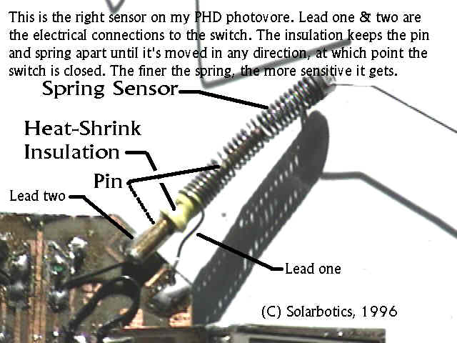
[1.3] Sensors and Nv Networks
Q: In "Living Machines", what is the reference "Nu neurons" referring to? I don't believe they are Nv nets, for they are mentioned separately. So what is the distinction?
A: The basic distinction is in what they are doing. You are right in assuming they are higher function neurons that effect the behavior of the base Nv network. A practical difference is that Nv and Nu neurons are laid out a bit different-basically swap the resistor and the capacitor so you have resistors running between output and input and capacitors tied to ground. Along with the original topology it gives you an integrator and a differentiator. Combinations of the two give higher function (but are a bitch to tweek).
Mark's early machines, such as Lobster, had Nu Nets Controlling Nv Nets. The damn thing kept falling over. Thus, Mark had to back track to more simple designs such as Walkman (which by the way was the genius of the True "MicroCore") in order to understand the behaviors that make everything possible. Fact is Nv net tech at its basic level very simple, but at the behavioral level it's much more complex.
A semantic difference is that "living machines" was written two and a half years (2�) ago and definitions have since then been redefined. The idea of calling MicroCore tech a "neural" net has been dropped since we managed to show that "Nervous net tech" is all that is needed when describing these things.
We've found using terms like "Master" and "Slave" more accurately reflect the separations in Nv tech.
Q: "Living Machines" talks about slaving an Nu with an Nv. Lobster has sensors that are processed by a neural layer that gives secondary stimuli to the Nv net. How do I connect an Nu to an Nv neuron and what is that circuit?
A: Below in figures 1 and 2 you will see the circuit and brief explanation of operation/use of both flavors of Nu (Nu+ and Nu-).
Figure 1: Nu+
  ^    ^            U1 - Schmitt inverter ('HC14) Do Not Substitute!
  |    |               (Well, not unless you know why you want to.)
  |    |            C1 - 10 uF  (for starters)
  \    |            R1 - 1 M    (raise value for longer activation)
  / R1 |            R2 - 100 k  (lower value for greater sensitivity)
  \    = C1         SW - normally open switch (whisker)
  /    |
  |    |    U1
  o----o---|>o----> to NV (or whatever)
  |    |
  :|SW |            Test results (with Low Current LED Vcc to U1 out)
  |    -            (all timings counted with loud cool music playing,
  \    ^ D1          and not measured; do your own testing)
  /    |
  \ R2 |            2.5 seconds to activate when SW closes
  /    |            15 momentary 'touches' to activate
  |    |            8 to 10 seconds to recover
  V    V

                  change R1 2.2 M
                         R2 10 k

                  2 momentary touches to activate or 'just about now'
                  15 to 28 seconds to recover
Symbology
Figure 2: Nu-^ ^ U1 - Schmitt inverter (74HC14) Do Not Substitute! | | (Well, not until you know what you're doing) | | C1 - 10 uF (for starters) \ - R1 - 1 M (raise value for longer activation) / R2 ^ D1 R2 - 100 k (lower value for greater sensitivity) \ | SW - normally open switch (whisker) / | Note resistor changes! | | U1 :|SW | | | o----o---|>o----> to NV (or whatever) | | | | Test results (with Low Current LED Vcc to U1 out) | | (all timings counted with loud cool music playing, \ = C1 and not measured; do your own testing) / | \ R1 | 2 seconds to activate when SW closes / | 12 momentary 'touches' to activate | | 12 to 15 seconds to recover V VSymbology
Note that the timings change from Figure 1 to Figure 2.D1 discharges C1 (to V(diode-forward)) when Vcc drops. This is important if Vcc for this circuit segment is being switched by other circuits, or if R1 is very high value. If you are not using D1 replace it with an open circuit. (a short to Vcc at U1(in) will affect your recovery time :-) )
Why an Nu? It pre-processes the input from your sensors. Let's presume that you've got a whisker to activate reverse on your 'bot. Nu lets you ignore activations that are too short (like if you bump the table and the whisker triggers once) and gives a minimum reverse time once triggered.
Things to keep in mind when you are changing the values in an Nu:
- R1 and R2 voltage divider must allow state change at input of U1
- R1 >> R2 gives faster triggering and longer activation
- R1, C1 and U1 hysteresis determine minimum activated time
- C1 increases trigger time and activation time
- U1 output must not be overloaded
Note on ASCII circuit conventions: The "^" and "V" are approximations of the arrowhead symbols sometimes used to represent Vcc and Vee, or "power" and "ground." Vcc is "power" is "positive" is the "up arrow." Vee is "return" is "negative" is (in this case) "ground" is the "down arrow." Someday maybe, I will convert most if not all of the circuits shown on this site. However, don't hold me to that, there is too much building to be doing.
Use the PNC (pulse neutralization circuit) from the patent, or a pulse initialization circuit if you have designed with the default state as no pulses. These two circuits limit the number of processes in the following manner: The pulse neutralization circuit is driven by an integrative neuron that has a relatively long (at least in comparison to the MicroCore loop) time delay. When the power first hits the circuit, the output of this neuron (which isn't your usual, everyday, MicroCore differentiating neuron) is immediately and reliably such that the pulse neutralization circuit is in process-eating mode. Thus, even though the MicroCore has powered up saturated, the pulses fail to get past the neutralization circuit. Finally, the integrative neuron saturates and its output drops. The last process to enter the neutralization circuit is then released, thus permitting one and only one process in the MicroCore. I am not sure how one designs a nervous neural loop such that its default state is no processes, so perhaps someone can write me about that. However, given that such a beast is possible, once again you'd probably have an integrative neuron, this time with a relatively short delay controlling the pulse initialization circuit. Since the integrative neuron is only going to saturate once (i.e., when its capacitor is completely charged. what is there to discharge it?) then the initialization circuit would generate only one process. I seem to remember a diagram that showed a diode or three that I didn't initially understand -- someone then told me that it was a way of reliably discharging the integrative neuron's capacitor once the power had been turned off.
Q: How do you modify a nervous net so that you can make a 2 motor, 4 legged creature turn if the bump sensor contacts something?
A: You'll find that the two motor variation is a great introduction to MicroCore building, and leg-geometry tuning. It is not the most agile design, though. They tend initially to be inclined to turn one way or the other, and you can tune the design to stabilize it. Reverse is no problem, but choosing a turn left / turn right might be best left for a subsequent design.
On the other hand, Andrew Miller has a robot with an unusual and effective method of turning: the front motor can spin right around. So when it runs in to something, a timer (Nv) keeps the front motor spinning in one direction for several revolutions. The robot turns almost "on a dime."
Q: Could you make a solar powered walking robot phototropic by adding some photoresistors or small solar cells to the front of the robot, and then connecting them to the MicroCore somehow? How does that affect the feedback from the motors to the MicroCore?
A: Yes, but one has their choice of two basic principles: resistive and photovoltaic. If you remember the diagram for a nervous neuron, there is an input capacitor and a resistor tied (nominally) to ground. I say (nominally) because it is possible to tie it to Vcc, or even have two resistors with the actual input to the gate (i.e., just AFTER the capacitor) be the center of a voltage divider. So, what can you do? If you were, for example, thinking of using an IR detector or a cadmium-sulfide (CdS) cell, you could put that in parallel to the normal resistor, in series with it, or even connect it to Vcc. If your sensor ends up lowering the resistance to ground, then processes going through the neuron do so with less delay (and possibly shorter pulse-width.) Fortunately, the contrary is true (more resistance -> longer delay.) Connecting it to Vcc has other effects that you'd basically have to work out (no light, some light, awful dam bright). If you have a resistance to Vcc that is pretty much the same as the resistance to ground, you end up with what Tilden calls a latch - if a process comes in, it potentially changes the output of the neuron and then the neuron stays in that state. Well, forever (or until your sensor changes or the battery dies) As far as photovoltaic sensors are concerned, well, they are obviously not just resistors. To be truthful, I've only thought about their electronics a little bit. Now, the really cool part is this: say you've put two photoresistors onto your MicroCore on the "front" two nervous neurons. Just what, exactly, happens then? It may seem that it would be as easy as "well this process ought to be shorter so this leg doesn't swing as far and the opposite side does so it turns toward the nervous neuron that has the sensor with the light," but it is much more complicated than that. The controls are not obvious, then you get into complexity and chaos theory and I'm certainly not capable of discussing that subject.
The circuitry to extend the process duration for a given Nv:__switch(sensor) Diode 10M or so +ve--------||------------o-------|>|-------/\/\--->input of NV | = Cap 1-1000 �F | grnd---------------------oBecause the Nv input draws so little current the discharge on the large cap will keep the process up and running for much longer than usual. In fact by repeating the diode and resistor for each Nv you can affect a whole MicroCore. You can actually use another MicroCore Nv to act like the switch. This basic principle has been used to change the gate and reversing some walkers. If you want to shorten the process duration, just change the polarity and flip the around the diode.
If you want to introduce a process to a Null MicroCore via a Photodiode try the following circuit:
_________ 1381E Voltage trigger (Digi-key) Photo Diode 1M Trim | | +ve---|<----------/\/\----2 1------||---->|---input of NV | | | .01�F Diode | ---3--- | | 0.1�F Cap --- | --- | | | grnd --------------*----------*by playing with the trim pot, you can adjust the light level at which the voltage trigger fires.
Below shows a method of attaching a touch sensor to speed up a process traveling through an Nv neuron:
              from
              last----||----*----|>o---------O
              neuron  C1    |    U1         Out
                            |
                             >
                            <
                             > Rt
                            <
                            |
                           Gnd

where Rt would be a serial combination of resistors R1 and R2, depicted
below:
                |
                |
            R1   >
               <
                 >
               <
                |
                *------
                |     |
            R2   >    |
               <      |
                 >    :| SW1 - N.O. Switch-touch sensor
               <      |
                |     |
                *------
                |
                |
               Gnd


   R1 = 1 MegaOhm
   R2 = 1.5 MegaOhm
   SW1 open Rt = 2.5 MegaOhm, closed Rt = 1 MegaOhm
If the sensor ends up lowering the resistance of Rt, then processes going through this Nv neuron do so with less delay; If the sensor ends up increasing the overall resistance of Rt, this creates a longer delay for processes traveling through this neuron.
Q: What do the plus or minus symbols next to the tactile sensors do to the processes within the MicroCore (in reference to Tilden's Paper Living Machines, Figure 5--the VBug 1.5 "Walkman" Complete Neural "MicroCore" Structure) ?A: Where there is a - they change the time delay across that neuron downward ("Inhibitive"), where there is a +, they extend the delay ("Excitatory"). They do not create or destroy pulses (or processes), only change their propagation properties.
Q: How do I change the length of a process?
A: There are several ways of modifying the length of a pulse through an Nv Net. One way to change the length of a pulse is to change the values of the resistor and capacitor that determine the time delay. Making the resistor bigger increases the time length by charging the capacitor slower, and making the resistor smaller makes the capacitor charge faster, decreasing the time length.
This methodology could be used as sensory perception, within the Nv Net, by attaching tactile sensors to the Nv neurons and have them modify the resistance, thus modifying the length of the pulse when the tactile sensor is triggered. This is great for making your robot adaptable to surrounding terrain.
Note: that these tactile sensors are attached directly before the inverter of the Nv Neuron.
Q: Tilden's patent has a robot in it that uses a multiplexer as a way of controlling the gait of the robot. What is a multiplexer and how does it change the gait of the robot?
A: A multiplexer is an electronic switch. In Living Machines, the multiplexer is symbolized as:
and is used to make the robot go backwards. This is facilitated by reversing the connection of the motor(s) to the MicroCore, this is where the multiplexer comes into use, by serving as an electronic DPDT (double pull, double throw) switch.
Q: The 74HC244 is configured as a reversing multiplexer, and a multiplexer is a sort of DPDT switch. So, when the sensor connected to the front of Walkman hits a wall, it makes the 74HC244 act like an electronic switch somehow. This reverses the polarity of the "waist" motor and makes the bug go backwards. How long does it go backwards like this or does it have another switch on the back end that makes it go forward again? More importantly, how is the 74HC244 configured to make it act like a switch?
A: Since the 74HC244 is a buffer, it has a pair of directional enable lines. Simply use an RC circuit that quick-charges thru a diode on activation (from the touch sensor), which switches the MUX on, then stays on until the RC drains down to a voltage where it goes back into default mode (forward).
A somewhat more detailed circuit follows:Vcc | | :| N.O. switch (press to reverse) | | U1 o-----o------|>o-----o To reverse enable of 74x244 | | / | \ R1 = C1 / | \ | | | Gnd GndChoose R1 and C1 for the reverse time you want. Add optional R2 from switch (such as this touch sensor) to Vcc to reduce sensitivity. The inverter 'digital-izes' the analog signal from the RC timer/switch.
You will find, below, the 74x244 info as found the "Great Internet IC Masturbator".
   74244 - Dual 4-bit 3-state noninverting buffer/line driver.

        +---+--+---+
   /1OE |1  +--+ 20| VCC
    1A1 |2       19| /2OE
    2Y4 |3       18| 1Y1
    1A2 |4       17| 2A4
    2Y3 |5  74   16| 1Y2
    1A3 |6  244  15| 2A3
    2Y2 |7       14| 1Y3
    1A4 |8       13| 2A2
    2Y1 |9       12| 1Y4
    GND |10      11| 2A1
        +----------+
Now how to hook the 74x244 up as a multiplexer:Pins 1 and 19 are enable pins, and when pin 1 (/1OE) is enabled, all of the pins with 1 as a prefix are enabled. Same is true for pin 19 (/2OE). Note that pins with an "A" in them are the inputs, and the "Y" is the output. So during normal operation, pin 1 is enabled, and when reversing, pin 19 is enabled.
Using the timer circuit from above, with the resistor, R1 being varied to determine the reverse time. Now connect the output from the circuit above (where it says To reverse enable of 74x244) to pin 1 of the 74x244 and to the Base (p) of a (general-purpose NPN transistor) 2N3904 though a 2.2K Ohm resistor, with the collector (N) being connected to pin 19 of the 74x244. Place a 20k resistor from pin 19 to +ve, and the emitter (n) of the 2N3904 to ground.
See circuit below:
|------------------------------------------o----------Now inputs 1A1-1A4 should be wired in pairs and connect to run the motor for forward operation and 2A1-2A4 wired to the same neurons but set up to go backwards.N n---------grnd 1A2 |4 17| 2A4 | 2Y3 |5 74 16| 1Y2 \ 1A3 |6 244 15| 2A3 / 20K 2Y2 |7 14| 1Y3 \ 1A4 |8 13| 2A2 | 2Y1 |9 12| 1Y4 +ve GND |10 11| 2A1 +----------+ N p - NPN transistor (N = collector, p = base, n = emitter), e.g., 2N2222, 2N3904 n
Symbology
Q: Is there a circuit that senses when the nervous network goes into saturation and resets the circuit via the PNC?A: from Terry Newton
                                              :  |
                                  __          :  R
          __                .----\  \         :  |  |\
 x >-----\  \               |     )  O---|<|-----*--| O-- ) O--------------*----/__/ : _|_ |/ y>-----/__/                                 : -.-
                                              : _|_ existing
                                              :     PNC
- x, y - outputs from two opposing microcore nodes
- diode - 1N914 or 1N4148
- NOR gates - 4001 (ground unused inputs) or 7402
- Should reset the PNC whenever the microcore saturates.
A bit of insightful commentary from Tom Edwards:
Once upon a time there were only bipolar transistors and things were ok. Engineers hated how much power they used and grumbled about getting rid of the heat but, basically they were happy because they had these neat integrated circuits that performed many interesting functions for them.
In any case, the world was full of transistor-transistor-logic (TTL). To send signals out of the output pins of these integrated circuits they decided on a structure called a "totem pole" because (in its most basic form) it looks just like the ones you see in NorthWest USA - with one figurine sitting on the shoulders of another. In this case it would be one transistor sitting on top of the other, and the pin would connect to the place where they came together - the emitter of the upper transistor and the collector of the lower transistor.
If you were to draw this out you might find it very familiar because it looks remarkably like one half of an H-bridge, and basically it is. One chose to look at the transistors as if they were perfect switches that connected to output pin to +5v or ground, depending on how you set up the signals that went into the bases of the transistors. Of course, it had the usual "smoke" protection kind of stuff, because it is a very bad idea to connect +5v to ground through your integrated circuit.
There were circumstances, however, where you didn't need the output pin to source current. This means that you don't need the top transistor at all and what remains: the bottom transistor that can sink current to ground for you. Since the output pin was connected to nothing much more than the collector of that transistor, it was called "open collector." It was cool for some kind of circuits - as long as you supplied a pullup resistor (something on the order of 4.7K Ohm, connected to +5v) then you could hook up two of these outputs together. If they were both off, that connection would more-or-less float up to +5v. However, if either of the outputs were turned "on", the voltage would drop to whatever value Vce(sat) was. Voila! An OR gate and all you had to do was add a resistor. This may seem a bit off topic, but if you look at Terry Newton's auto saturation neutralizer above, it is particularly relevant. Both the 4001 and the 7402 are quad NOR gate chips, but since one is bipolar and the other CMOS I guess they decided that screwing around with the pinout was a good idea. In any case, the NOR in the middle has both of its input lines tied together. As a result it acts simply as an inverter: put high in, it will give you low out and vice versa. What it really does is invert what is coming out of the left hand NOR gate. Now put the gates together and you have an OR gate (for all intents and purposes). You will recall the truth table for an OR gate looks like:
     x y  out
     0 0   0
     0 1   1
     1 0   1
     1 1   1
Now you will recall that nervous neurons provide active-low outputs, thus we can conclude that if this circuit sees an active-low on both the x and y inputs that it will provide us with an active-low output but not at any other time (this is important.) For a 4 neuron loop, if opposite neurons are active, then you've got SOME kind of saturation (there is more than one form) so if you hook up x and y to those opposite neurons, you would now know when the circuit was in saturation.Perhaps you've seen diode symbols strewn about circuit diagrams and sometimes they seem to make sense and other times they don't. Well, if you use a diode such that its cathode (the banded end) is connected to the output of an integrated circuit, the anode of that diode looks a whole bunch like an open collector! Once again we have a circuit that can sink current on command but can't source it. As Terry indicated that there may be an existing PNC circuit built into the robot - and it turns out we can use this 'open collector' kind of signal to connect to its input, probably in parallel to some reset switch somewhere. That way you can either use the switch to reset the loop OR (recall the "wired OR" concept from above) you can rely on the auto saturation neutralization circuit - and they won't get in each other's way.
Brian O. Bush / bushbo@mediaone.net
Updated: Oct. 25th, 1998