The SunEater Series of Solar Engines
To learn more about solar engines, please visit the parent page on Solar Engines in general. However, I highly recommend building these circuits first (SunEater_II, then SunEater_I) because of their simplicity in operation and robustness.Contents
- Introduction
- SunEater I
- SunEater II
- SunEater III - a photovore based on a modified SunEater II
- Abbreviations
- Testing a SunEater
- Comparison with other solar engines
Introduction
Steven Bolt, a talented BEAM enthusiast from the Netherlands set out and designed a couple high-efficiency Solar Engines (SE), with the main goals:- a circuit anyone can build
- that always works well
- no specialized components
SunEater I
SunEater I Circuit
SunEater I Layout
Performance
The motor is switched on when the 47,000µF cap reaches 2.1V, and off when the voltage drops below 1.2V. This gives good economy for pager and small recorder motors. About 100mA is available at switch on, so even fairly reluctant motors and not quite ultralight `bots should move.The solar panel needs to supply just a few tens of µA to cause an occasional run. Put in another way: the prototype has been happily running in the window sill from full sun (old recorder motor continuously purring) to a little after sunset. It's now occasionally running below a 6W PL lamp on my desk.
Pinouts of transistors used in SunEater
A few comments about the circuit
With a single green LED to determine the switch-on level, the motor will start when the 47,000µF cap reaches 2.1V, and stop when the voltage drops below 1.2V. This gives good economy for pager and small recorder motors. If your motor or other device likes a higher voltage to begin with, you may put something in series with the green LED.Switch on levels: Green LED and a 1N4148 (small silicon diode) in series: 2.4V Green LED and two 1n4148's in series: 2.7V Green LED and red LED in series: 3.7VThe switch-off level remains about 1.2V.
The following table contains a list of parts you will need for the SunEater_I.
| Quantity | Reference | |
| LED | Regular Green LED | |
| Q1, Q3 | 2N3904 or BC549 NPN transistor | |
| Q2 | 2N3906 or BC559 PNP transistor | |
| Q4 | 2N2907 or BC327-25 or 2N2905 PNP transistor | |
| 470K | 470K Ohm resistors | |
| 10K | 10K Ohm resistors | |
| 100K | 100K Ohm resistors | |
| 1M | 1 Mega Ohm resistors | |
| 47N | 47 nanoFarad capacitor | |
| 47,000 µF | 47,000 µF electrolytic capacitor | |
| M | Any sort-of-efficient motor, like a pager | |
| Solar Panel | Solar Panel that generates over 2.1 Volts unloaded |
SunEater II
The common or garden Solar Engine appears to be difficult to repeat. The circuit and the builder may both be to blame. Other, better performing Solar Engines have been based on difficult to obtain and none too cheap parts. To avoid all these problems Steve aimed at: easy to build; cheap, common parts; good performance. SunEater_I achieved that, I think. SunEater_II does much better!Comparing the circuit diagram (and PCB layout) below to Solar Engines in general:
1) SunEater_II may look complex, but at 15 the parts count isn't bad and the price is right - the 74HC00 at about $0.4 being the most expensive bit. Actually, it's about as cheap to build as SunEater.
2) The performance is very good; SunEater_II will run in 1/3 the light that SunEater needs, and is about twice as 'active'. (And SunEater isn't at all bad :)
3) SunEater_II is probably even more reliable and easier to build than SunEater. Use the specified parts and the circuit will work, with that one adjustable resistor in any position. It's there just to get the most out of your motor or `bot. Things will move regardless of adjustment.
4) This concept is not limited to being a common or garden solar Engine. It can be the core of a CMOS-brained bot, which keeps 'thinking' in light (almost darkness) that is not sufficient for the motor to run. The output of N1 will signal the energy condition to that brain: a '1' meaning not enough, a '0' indicating plenty for the motor. But the brain may or may not choose to fire the motor, depending on other conditions.
SunEater II Circuit and Layout
And now a few words about the circuit
Solar Engines are fairly difficult to design, mainly because the voltage over the storage cap rises slowly. The voltage-conscious part of the circuit typically spends a lot of time hesitating between yes and no. That is a bad condition, because it makes the semiconductors (ordinary or CMOS) leak current. Circuits are efficient when outputs are either high or low, with fast switching in between. Put them at the high/low edge, and things go badly.
SunEater_II tackles this problem head-on. No matter how long the in-between condition, the circuit spends at most 0.5% of its time looking at it. Let's see how it works.
The inverters N1 and N2 (CMOS NAND-gates used as inverters) together form a schmitt-trigger, which checks the voltage over the storage caps as presented by the diode (3 x 1n4148) and resistor (500K pot plus 100K) junction. Ordinarily, this would result in a slowly rising current used by the circuit itself - not going into the storage cap - as the trigger point is approached. here, that rise is almost completely avoided by 'sampling' the voltage, rather than measuring it continuously. N3 and N4 together form a pulse generator, which supplies about 5 pulses a second, each of them about 1/1000 of a second wide. Only during a pulse, does the schmitt-trigger look at the voltage over the storage cap.
When the stored voltage reaches the required value, the schmitt-trigger fires: N1's output becomes '0', thereby stopping the pulse generator in an output-high condition, and making Q1 and Q2 conduct, thus running the motor. When the voltage drops about 0.7 to 0.9 volts, N1's output returns to '1', the motor stops and the pulse generator continues.
The entire 74HC00 with pulse generator running consumes only about 10µA, considerably less than the current consumed by most Solar Engines when approaching their trigger point. For this reason, very little light is needed to run at all. In darkness, If I aim the beam of a 3-penlite flashlight at SunEater_II (from more than a meter distance) it runs briskly. For the minimum amount of energy, we're talking less than candlelight.
A more important advantage of the sampling approach is the freedom we gain to design the trigger. It doesn't need to be overly sensitive. The switch-on and switch-off levels can be selected as needed (but please build your SunEater_II using the values in the diagram before trying anything else).
Note that N1's output need not be directly connected to a motor driver. By careful design, it is entirely possible to have a fairly large number of CMOS logic functions consume only a few tens of micro-amps; a 'brain' can be designed, which takes the N1 output as one of its criteria for firing any one of several motors. While 74HC logic is specified to function at Vcc between 2 and 6V, the chips actually do quite well at much lower voltages. Even the lowest switch-off level of SunEater_II (1.6V) leaves a high enough voltage for your robot's 'brain' to keep on thinking...
The following table contains a list of parts you will need for the SunEater_II.
| Quantity | Reference | |
| 1N4148 | 1N4148 small signal diodes | |
| 74HC00 | 74HC00 (NAND gates) CMOS integrated circuit | |
| Q1 | 2N3906 or BC559 PNP transistor | |
| Q2 | 2N2222 or 2N2219 or BC337-25 NPN transistor | |
| 2M2 | 2.2 Mega Ohm resistors | |
| 500K | 500K Ohm variable resistor | |
| 220K | 220K Ohm resistor | |
| 100K | 100K Ohm resistor | |
| 47K | 47K Ohm resistors | |
| 1K | 1K Ohm resistor | |
| 100N | 100 nanoFarad capacitor | |
| 10,000 µF | 10,000 µF electrolytic capacitor | |
| M | Any sort-of-efficient motor, like a pager | |
| Solar Panel | Solar Panel that generates over 3.0 Volts unloaded |
Note on the Capacitor Used
Why does SunEater_II use a storage capacitor of 10,000µF, and not 47,000µF like the first SunEater? The reason is that I have no 'Super Cap', or 'Gold Cap' or some such with a sufficiently low internal resistance to avoid a sudden voltage drop when Q2 switches power to a common pager or small recorder motor. Such a voltage drop would cause SunEater_II to immediately switch off - and try again, 5 times a second, without the motor turning as much as one degree.A capacitor with low internal resistance is always best and in this particular case essential. There are nice 10000µF caps with a 10V rating, 4cm long, 2cm diameter; not expensive and very good for SE purposes. An alternative would be two 4700µF caps in parallel.
If your application needs larger storage, you might consider using a really efficient motor. The ones I use on Spider run perfectly on a large Super Cap, because the motor's internal resistance is high, even when starting up. If you need to combine a Super Cap with a not so good motor, you might be best off with the first SunEater - it doesn't mind if the voltage drops a bit, mainly because its switch-off level is only 50% of switch-on. Of course you might lower SunEater_II's switch-off level, but I don't recommend that.
Note on changes made to SunEater_II
Apr 17, 1998Steve (the designer) wanted to make sure a full starting kick to the motor even with bad transistors was available, thus assigned Q1 a 10K base resistor. However, this will oversaturate good transistors. Steve hasn't found any transistors of the specified types which are bad enough to require such a low value.
This means you should see a worthwile gain in duration of the motor run if you use up to 47K instead. (It won't run more often, just a little longer when it runs.)
Note: This is not true for the 4-transistor SunEater_I, which had to be a much tighter design. Here Q3/Q4 won't oversaturate with the base resistor shown above.
SunEater III
This photovore is based on SunEater_II and uses 74HC logic to do all his "thinking." Two prototypes were built. The first one has motors which are very similar to those found in cheap servos. Number two is equipped with motors found in micro-cassette recorders. After adjusting the pots, they had almost exactly the same performance:
Performance
With the morning sun less than 30 degrees above the horizon, its horizontal BP243318 (24x33mm 5-cell panel) supplies enough power for one 'step' of about 1cm per second. When the sun gets higher, both prototypes achieve well over 1cm/s, which seems pretty good given their weight (78 and 98 grams), and the small size of the solar panel.
Even in full sunlight, it keeps looking for something better while trying to avoid shadow patches. And SunEater_III truly backs away from obstacles (without reversing motors) like my clock-powered photovores do. This page explains how.
In low ambient light conditions, you still get the occasional step, as the thinking part uses only about 20uA or less. Very little current when compared with, for instance, the typical self discharge of a 0.047F 'Super Cap', which is something like 70uA (larger Super Caps will usually discharge even faster, so it's rather fortunate that SunEater_III needs an ordinary 4700uF storage cap). Thanks to the 'mechanical memory' - SunEater_III keeps a feeler in contact with an obstacle during evasive action - the motion remains deliberate, even if the voltage drops to zero between steps.
Circuit
SunEater III Circuit
In the schematic above you see a SunEater_II pulse
generator (built around NAND gates N3 and N4) and voltage
monitor (N1/2). As long as the voltage over the storage cap
(4700uF) is lower than the switch-on trigger level, the
pulse generator runs, which means that the voltage monitor
'samples' the voltage about 5 times a second, each time for
about 1 millisecond. This prevents the rather high current
consumption normally associated with having almost any
trigger device hesitate between yes and no for a long time.
When the solar panel has charged the storage cap to the required
level, N1's output becomes low (about 0V), forcing N3's output
to remain high. This means that the schmitt-trigger is now
continuously monitoring the stored voltage. It's output will
therefore keep one of the motors running until the voltage drops
below the switch-off trigger level. Without the feedback from N1
to N3, the motor would be running only for the duration of a
sample pulse.
Which motor actually runs is determined by the schmitt-trigger built around the NOR gates N5 and N6. They take their input from the 'eyes' (the two BPW41 photo diodes) and the feelers. Note that the bias current for the eyes is also switched by the pulse generator, which makes it possible to use a small bias resistor (2K7) for good performance in full sunlight, without suffering excessive current consumption.
NOTE: both types of motor have a preferred direction of rotation; their connections are marked + an -. But the servo-type motors ran clockwise, while the recorder motors were found to run counter-clockwise. Wiring your motors up correctly may take a bit of trial and error.
PCB layout
SunEater III PCB layout
Above you see the layout and where the components are supposed to be. Note that the 74HC00 and 74HC02 each contain four gates, but do not have the same pinout. They are facing away from each other, with pin 1 (marked in some way on the case) closest to the nearest motor. For the BPW41's, the distance between the case and the PCB should be more than 5mm, so you can make them face 45 degrees down; that makes SunEater_III avoid shadow patches as well as look for better light further away. The storage cap hangs below the PCB (as can be seen on the photos). Its connections are marked 'elco+' and 'elco-'.
Note that you may well need to make the cut-outs for the motors fit your particular size.
Below, the layout is shown in black without the components. Shift-click on the picture to download a version in Postscript, and print that on transparent paper using Ghostscript and a laser printer (or a laser printer with built-in Postscript interpreter). The result will be a correctly scaled layout in high resolution, ready for transfer on UV-light sensitive PCB material. Make sure that 'Pitronics' comes out readable, otherwise you get the mirror image of what you need.
SunEater III PCB film (click on the image to download the zipped Postscript file)
Adjustment
Compared to SunEater_II, a second 500K pot has appeared in the voltage trigger. This makes the circuit very easy to optimize for any reasonable type of motor (begin your experiments with both pots centered). The Switch-on level is adjusted using the pot connected to the 100K resistor. The other pot adjusts the hysteresis (distance in volts between switch-off and switch-on) of the schmitt-trigger built around N1/2. What values you need are determined to some extend by the mechanical nature of your motors. Recorder types have a fairly large diameter, which gives the rotor considerable inertia when compared to for instance a pager motor.
High inertia means a current pulse needs to be relatively long to get the motor going. On the other hand, a large diameter also tends to give good torque at low rpm. In practice, the recorder motors worked best with a slightly lower switch-on level and a larger difference between switch-on and switch-off, when compared with the servo type motors (which have a much smaller diameter). If necessary, you can short one of the three 1N4148 diodes in the chain to get a lower adjustment range.
In general, Switch-on should be set at a voltage where the motor accelerates well. A higher voltage wastes energy - the 'step' will be shorter and the recharge time longer. Switch-off should occur when the motor is still just doing useful work. Such switching levels make the SunEater_III react properly when a feeler touches an obstacle, and give it sufficient push to handle terrain somewhat more difficult than a smooth tabletop. The prototypes handle a fairly steep incline and the rather substantial joints between my floor tiles.
The BPW41 'eyes' were balanced by covering part of the front of one of them with a bit of black tape.
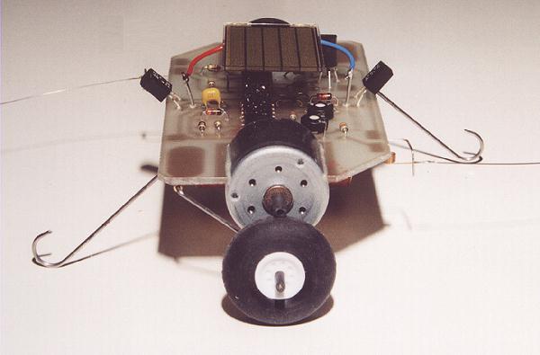
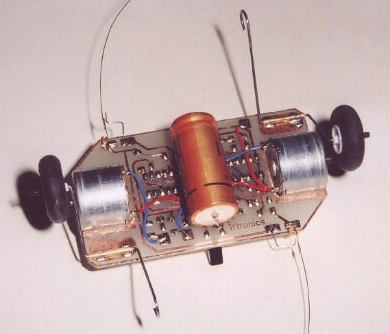
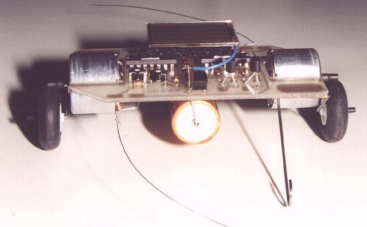
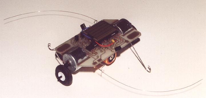
Mechanics
The shafts of the motors rest on little rubber-tyred aircraft wheels. That provides the required ground clearance, while keeping torque and speed as in 'direct drive'. The recorder motor shafts were made a bit thicker and longer with a piece of pvc isolation stripped from mains wiring. The very simple construction can be seen in the diagram below:
SunEater II Chassis
After careful shaping of the cut-outs,
the motors of the prototypes were glued in place using
epoxy. As to the weels and supports:
For the
prototypes I used 1mm steel wire. The bits of brass
tube had an outside diameter of 2mm and and measured 1.2mm
inside. You can find such tube and wire in a modelling shop,
or even in a hardware store. Cut the pipe by rolling it below
a Stanley knife (thus emulating a pipe cutter). After bending
the wire, the pipe should be clamped to the pcb in the correct
position, and soldered with your iron set to about 400 degrees
Celsius (normal temperature for soldering electronic components
is about 360 degrees). If you don't have a miniature clamp, you
might use a suitable pair of tongs with a rubber band around the
handles to keep them closed.
Because the aircraft wheels had
a rather wide plastic hole for the shaft, I drilled them to size
and pushed in bits of brass pipe by way of barings. The wheels are
held on their shafts with bits of pvc isolation stripped from wire.
When SunEater_III stands on its wheels, only one of the supports should
(lightly) touch the ground; the other should have some 5mm of float.
The feelers were made of 0.3mm steel wire. You can shape the curve by
drawing the wire across an edge. The springs were found in old recorder
motors, where they served as brushes. Of course you can wind integral
springs, but soldering a separate spring and feeler together is easier.
The contact is plain, tinned wire.
The solar panel is held in place using
a piece of black foam and double-sided tape.
I hope that the above information is sufficient for you to build your own Suneater_III. If not, you can ask me specific questions. Enjoy!
Abbreviations
For those of you asking "What is a 100N capacitor?", well here is some abbreviations defined. The 'N' stands for 'nF' or nano-farad. In the same fashion, a 'P' would mean 'pF', or pico-farad.While the range of letters one might use is longer, you'll mostly encounter:
Continuing for resistors:P (pico) 10 to the -12 N (nano) 10 to the -9 µF (micro) 10 to the -6 mF (milli) 10 to the -3
When appropriate, the letters can take the place of a decimal point. '2M2' means 2.2 mega-ohms, 2200000 ohms. Note that on any real capacitor, you are unlikely to read something as straightforward as '100N' or even '100nF'. For reasons obscure to me, it might be '100nS', or, somewhat less obscure, '104' (meaning 10 with 4 zeroes behind).E (ohms) K (kilo) 10 to the 3 M (mega) 10 to the 6
Testing a SunEater
When your SunEater is finished, you want to test it. If a real solar panel is not available, or if you want to simulate different panels, you can use a couple of batteries or a power supply. Always put a resistor in series like this:
Which becomes 560 ohms in the usual range of available values (the E12 range).
Now let's check some real performance figures.
In bad light - it is early morning here, with a solid overcast - the tiny 24 * 33 mm solar panel connected to my SunEater_II supplies 320µA at the 2.6V switch-on trigger voltage. We simulate that with a resistor:
Taking 8200 (8K2) from the E12 range. Of course, if we look at Solar Engine performance, we are interested in time rather than current. With a 10000µF storage cap, what charge time can we expect? The formula is:
In this case:
Counting from zero volts. More interesting is the time it takes to charge from SunEater_II's switch-off level (1.7V) to the switch-on trigger voltage. So we also calculate:
The time from switch-off to switch-on then becomes 60 - 34 = 26 seconds. Which is exactly what I just clocked. So at this light level, SunEater_II's own current consumption does not detract appreciably from the solar panel performance. In fact, using a very good current meter I can see that the circuit runs on less than 14µA.
The 4-transistor SunEater is a very different animal. For much of the charge period, the circuit consumes no current at all. But as it nears the switch-on trigger level, Q1 and Q2 start leaking a little current. In the end, the prototype circuit (using BC-type transistors) needs 55µA to get 'over the hump'. So in average or even fairly bad light levels, SunEater wastes on average as little or even less current that SunEater_II. But in really low light levels, SunEater_II clearly wins.
More important is the difference between the switch-on and switch-off trigger levels. A Solar Engine must switch on the motor when there is sufficient energy to give the attached device (`bot) a useful push. And it must switch off when the voltage drops to the point where the motor doesn't deliver mechanical power anymore, but merely wastes energy that must be recharged during the next cycle.
The 4-transistor SunEater needs a good motor to be useful, because
its switch-off level is rather low. SunEater_II not only has an
adjustable switch-on level, but the difference between switch-on
and switch-off is always less than 1V. It makes better use of even
not so good motors. And it always leaves a voltage higher than
1.6V - enough to keep a cmos 'brain' (based on 74HC-type chips)
running between power bursts. On the down side, it needs a storage
cap with a very low internal resistance, as is pointed out
elsewhere on this page.
Comparison with other solar engines
The Micro Power
Solar Engine by Ken Huntington in comparison to the SunEaters.
This design has a variable resistor which must be adjusted to assure reliable operation, making it slightly more difficult to build than the SunEaters. But with a maximum current consumption of about 12µA at trigger point, it is still the champ of the 4-transistor designs! When SunEater_II is tested at the same switch-on level (2.4V), it also consumes about 12µA. So at the lowest usable light levels, these two Solar Engines waste about the same minuscule amount of energy. SunEater_II has better overall performance due to its nicer and easily adjustable trigger levels.
this page was assembled with Steven Bolt's permission
edited and complied by Brian O. Bush / bushbo@mediaone.net
Updated: June 12th, 1998