Biology - Electronics - Aesthetics - Mechanics
Mallorca
named for the song by Loft
a machine in the garden by Brian O. Bush, bushbo@xtdl.com
Introduction
A solar powered walker based upon Tilden's nervous network technology - a microcore with motor drivers (a line driver, specifically the 74HC245). The walker itself is quite slow with a ON duty cycle of 5 seconds (resistor = 470k Ohm), and 2 minutes of OFF (resistor = 10 Mega Ohm) (charge time) - thus being idle. The cycle time is re-configurable by switching a header with two resistors located forward-top on the body under the solar panel. Using this header to control the oscillation time was very critical in creating an agile walker that can walk in moderate light to bright (of course, at a slow cycle). For close-up detailed pictures please see the following page which contains several large color images - so be warned.
Specifications
a 0.22 Farad capacitor-5 Volt, 4 Nv nervous network based on the HC version of the 7414 (0.1µF caps and 2 Mega Ohm resistors are used in the network), line driver as the motor driver-also HC, oscillating PNC that oscillates between the charge and walk state, MPJA gearheads, pager motors mounted with fuse clips, paperclips make up the legs, ball-link collars attach the paperclips to the gearheads, frame is a tinned heatsink from an old $9,000 dollar junk circuit board, heat shrink tubbing for traction on legs, spring to help limit leg motion and provide feedback to the Nv net is from a printer, solar panels are from Solarbotics, wire composing the free-formed MicroCore is from excess length wire from resistors and such (which to my supprise is quite structurally sound).
Nervous Neuron Structure
In>------||------*----|>o---------o Out
         C1      |    U1
                 |
                 \
                 / R1
                 \
                 /
                 |
                Gnd

where:
  C1      0.1µF monolithic capacitors
  R1      2 Mega Ohm resistors
  U1      a Schmitt Inverter (of the 74HC14)
Pulse Neutralizing Circuit Structure
         R1     D1
    ----/\/\/--|<|-|
    |              |
    |    R2     D2 |
    *---/\/\/--|>|-*
    |              |
    |    U1        |          D3
    *---|>o--------*---------|>|---o out 1 (to neuron 3)
    |              |
    |              |
    = C1           ----------------o out 2 (to pin 19 of 74HC245)
    |
   Gnd

where:
  U1      a spare schmitt inverter from the 74HC14
  D1-D3   are small signal diodes, namely the 1N914
  R1      10 Mega Ohm, determines the discharge time of C1-off or "rest" time
  R2      470k Ohm, determines the charge time of C1-on time
  C1      an electrolytic capacitor with a value 10 µF
Note: I have used a photodiode or photoresistor in some of my tests to control the value
of R1, the "rest" time, which allows this circuit to gauge how long it should
rest and charge based on the amount of light.
Central Pattern Generator Circuit Structure
      .------------o              o--------.
      |    .------ 2 <----------- 1 <-. | o="motor" drivers (74HC245) |+ | | +| Rear   | .------------------------'  Front
    Motor  `-|------------------------.  Motor
      |-     |                        |   -|
      |      `---- 4 <----------- 3 <-' | `------------o o--------'
The Pulse Neutralization Circuit (PNC) is tied to node 3. Upon nervous network activation the pulse travels from node 3
- 4 - 1 - 2 and then returns to node 3 where the sequence repeats. As a pulse travels
around the loop (illustrated above) it makes each the motor outs go low one at a time,
producing out-of-phase motions in the motors:
     motor          1      2      3      4      1      2      3      4
     ------------------------------------------------------------------
     front motor   CCW    off    CW     off    CCW    off    CW     off
     rear motor    off    CW     off    CCW    off    CW     off    CCW   repeats...
     active neuron  3      4      1      2      3      4      1      2
Note: only one motor moves at a time, since there is only one pulse moving about
in the microcore.
Walking Behavior
Walking is controlled falling. Period. The act of walking (for one limb) can be defined as follows:"The cyclic movement of a walking leg consists of two parts, the power stroke (also stance phase or support phase) and the return stroke (also swing phase or recovery phase). During the power stroke, the leg is on the ground where it can support and propel the body. In a forward-walking animal, this corresponds to a retraction movement of the leg. During the return stroke, the leg is lifted off the ground and swung to the starting position for the next power stroke." (Cruse 1990)The leg movement behavior is obviously cyclic, and thus can be attributed and controlled by a central pattern generator. In this machine this cyclic behavior was accomplished by the MicroCore and assisted by the rachetting mechanism of the four-legged body. The rachetting mechanism is mainly attributed to the front legs, while the back legs drag along serving to balance (and unbalance-instigating the controlled falling) the body.
Images
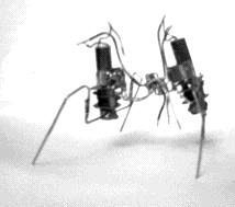
mechanical structure only
This is how Mallorca
looked before the brains and power source were added. The inspiration for this design
was the MPJA gearhead/motors were very power hungry. So following Dave Hrynkiw's lead,
I tore off the motor and replaced it with a pager motor. Then the frame came along and
was quite light and strong, as well as being quite solderable (metal was tinned). So with
a frame, motors and gearheads, all i needed was some legs. Lacking the right material being
the right size and composition, I used paperclips soldered to wheel collars from Dubro (see
any hobby shop).
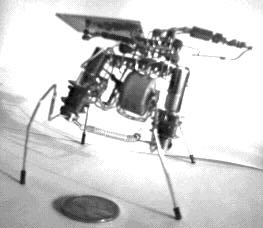
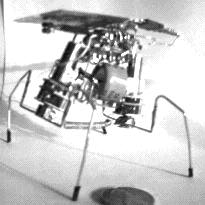
Side view (in
color)
This is a side view showing the physical layout of the free-formed microcore.
the 7414 is stacked on top of the 74245 which is right over the capacitor ridding on the
frame. The free-formed microcore is started and stopped by a PNC that was first shown to
me by Richard Weait, that is basically an slow oscillator.
Also, note the size of the penny in the foreground.
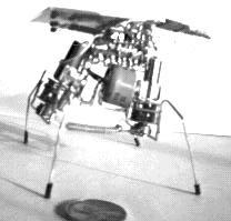
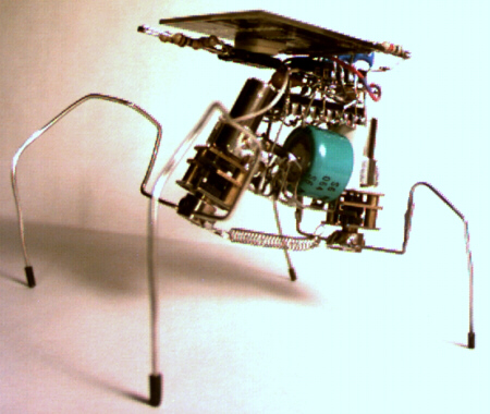
Side view
The spring, shown above between the wheel-collars connected to the gearheads, provides the
necessary feedback to the microcore - as to not move its legs to far forward or backwards.
This mechanism is also found in natural organisms with simple muscles being used as sensors
for relying on the basic "overstrain damage limiting sense" for feedback. Also aside from
the spring, the legs act as a spring to provide feedback too.
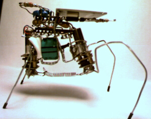
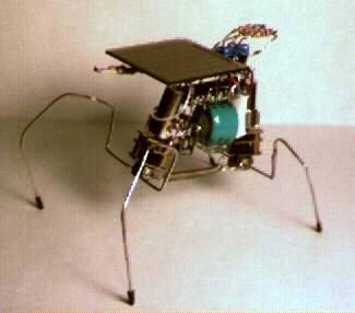
Side view at angle
Note the construction of the legs. After getting the gate tuned (which was also done by a
four resistor header - Plug and Play), the next step was to get the legs configured
so as to rachet over desk obstacles. Mallorca cannot handle more than a sheet or two of paper
obstacles due to the clearance of the legs, but more importantly that nervous network
technology is quite powerful in making a solar walking machine. Future developments in both
circuit, storage (capacitors) and solar cell technology will provide much greater power to allow faster walkers
with more strength and agility.
Top-down view
You will note in this image as in the top, there are different front legs than in the
other photos. This is possible using an idea i got from Richard Weait to use Dubro wheel
collars so that I can swap legs. A very handy feature when experimenting with different leg
types.
Future
Well, as Tilden has said, once you have finished one move on to the next. So in that spirit I am not going to enhance or change Mallorca, but instead take my ideas to the next walker. One being a photovore based on a two-motor microcore walker. The idea being the walker would have two light sensors, one in the front and one in the rear. These sensors will detect the brightest source of light and using a 74244 as a multiplexer move forwards or backwards. Since a walker rarely walks perfectly straight, over time, you will have a random walk eventually moving towards the brightest light source.
References
- The BEAM FAQ
- The BEAM Tek site
- Andrew Miller's site, a great explaination of the microcore and creating a microcore walker (including debugging and stabalization of the final walking machine)
- Cruse, H. (1990) What mechanisms coordinate leg movement in walking arthropods? Trends in Neuroscience, 13:15-21.